Matlab code for implementation of Fourier Transform and Inverse Fourier Transform of bit stream.4/5/2014 ExplanationDiscrete Fourier Transform also called DTFT is the frequency domain representation of the signal having discrete signal as an input. This discrete input signal could be produced by using sampling process on continuous signals. It is a frequent requirement in signal processing, for the detection and analysis of frequency components that are of interest, even when accompanied by unwanted stronger frequency components. A Fast Fourier Transform is only one of the many available algorithms and techniques for achieving the transformation with a considerably smaller amount of mathematical operations and hence is much faster than the direct implementation. The applications for FFTs are numerous and diverse. For many types of functions it is possible to recover a function from its Fourier transform. Intuitively it may be viewed as the statement that if we know all frequency and phase information about a wave then we may reconstruct the original wave precisely. The inverse Fourier transform is extremely similar to the original Fourier transform: as discussed above, it differs only in the application of a flip operator. For this reason the properties of the Fourier transform hold for the inverse Fourier transform, such as the Convolution theorem. Matlab Code% Matlab Code to implement Fourier Transform and Inverse Fourier Transform 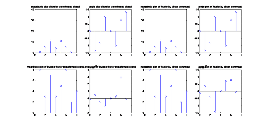 Fourier Transform and Inverse Fourier Transform of Bit Stream
0 Comments
ExplanationQuadrature phase shift keying is a modulation technique used for modulation of digital signals. In Quadrature phase shift keying four levels of voltage are used or four carrier signals of different phases are used. In following code simply the indexes of digital signal array are checked (two indexes at the same time) by using for loop and then depending upon bits carrier signal is changed, thus producing our desired results. It is checked that the two bits are (00, 01, 10, 11) and then carriers of different phases are assigned accordingly. Matlab Codeclose all; 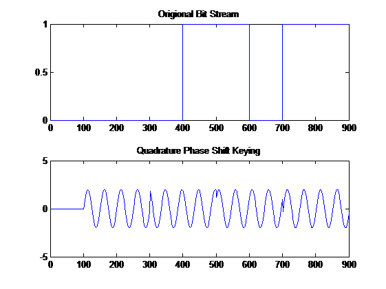 QUADRATURE PHASE SHIFT KEYING ExplanationBinary phase shift keying is a modulation technique used for modulation of digital signals. In binary phase shift keying two levels of voltage are used or two carrier signals of different phase are used. In following code simply the indexes of digital signal array are checked by using for loop and then depending upon bits carrier signal is changed, thus producing our desired results. Matlab CodebitStream=[1 0 0 1 1 0 1 1]; 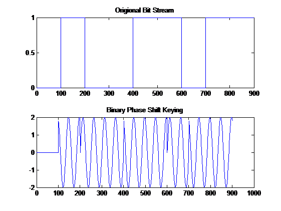 binary phase shift keying PULSE WIDTH MODULATIONA modulation technique in which pulse of the carrier signal is changed in accordance with the amplitude comparison of message signal with carrier signal. Code ExplanationA message signal of particular frequency is defined then carrier signal of the form sawtooth is defined. Now desired result is obtained by comparing the amplitudes of message and carrier signals i.e if message signal is less than carrier signal pulse of output signal is zero otherwise pulse of the output signal is one. Matlab CodefrequencyMessage=50; 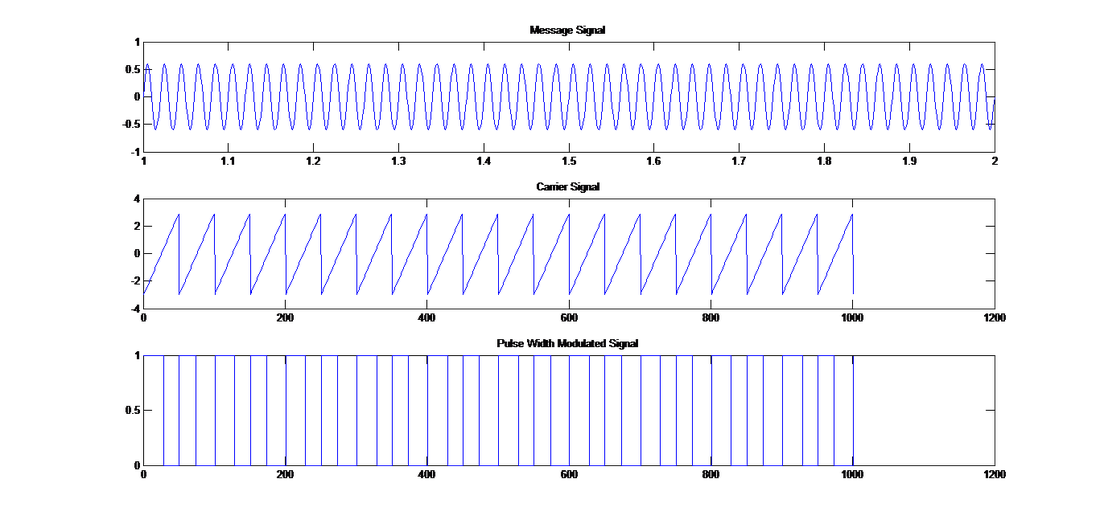 PULSE WIDTH MODULATION Frequency Shift Keying Code ExplanationIn frequency shift keying the amplitude of the resultant signal is varied in accordance with the input bit sequence that we have defined. If the bit sequence is 0 the resultant signal is an analog signal of a defined frequency 20 for a defined range of time. If the bit sequence is 1 the resultant signal is an analog signal of a defined frequency 50 for a defined range of time. Matlab CodebitStream=[0 1 0 1 0 0];%defining a bit stream 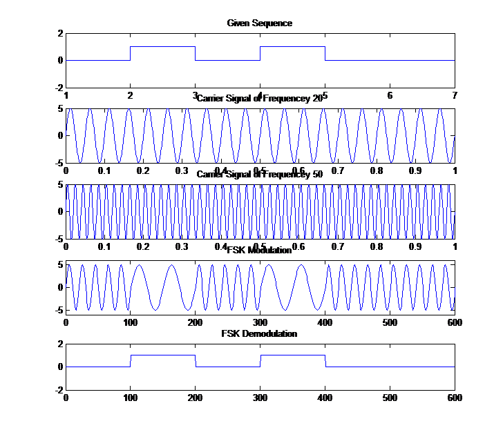 FREQUENCY SHIFT KEYING MODULATION AND DEMODULATION Amplitude Shift KeyingIn amplitude shift keying the amplitude of the resultant signal is varied in accordance with the amplitude of the input bit sequence that we have defined. If the bit sequence is 0 the amplitude of the resultant signal is zero otherwise the resultant signal is an analog signal of a defined frequency for a defined range of time. Matlab CodebitStream=[0 1 0 1 0 0];%defining a bit stream 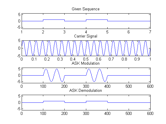 AMPLITUDE SHIFT KEYING MODULATION AND DEMODULATION. Under Sampling?Now decreasing the sampling rate of already sampled signal is called the process of under sampling (down sampling). In some applications we require under sampling. Two different methods are used for this kind under sampling (down sampling). Following code and output shows the concept explained. Matlab Codef_origional=60; 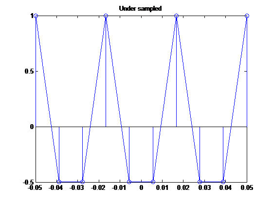 Under Sampling Or Down Sampling MATLAB Code Over SamplingNow increasing the sampling rate of already sampled signal is called the process of up sampling. In some applications we require upsampling. Two different methods are used for this kind over sampling (upsampling). Following code and output shows the concept explained. Matlab Codef_origional=60; 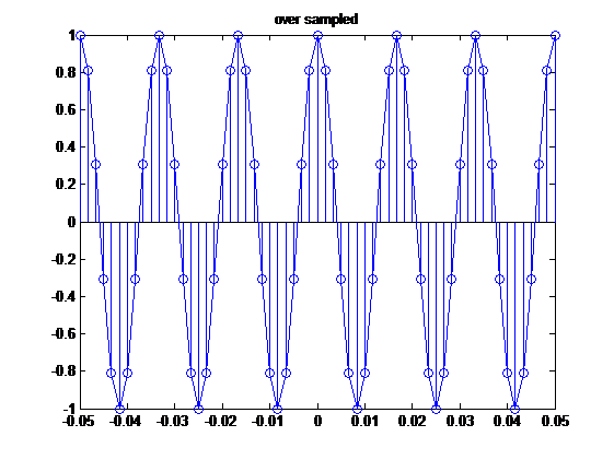 Over Sampling Or Up Sampling MATLAB Code Sampling ProcessWhen sampling process is done by using Nyquist criteria to avoid aliasing i.e the sampling frequency should be two times the frequency of the origional signal, the this is called Nyquist Sampling. Following code and its output shows the concept explained Matlab Codetime=-.05:.001:.05; 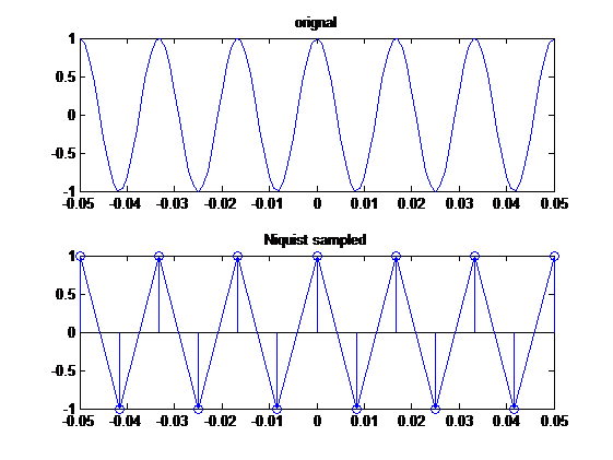 Sampling Process Using Nyquist Criteria Bipolar Coding Scheme?Bipolar coding scheme is a type of line coding (a technique of converting digital data to digital signals). In bipolar coding scheme a ‘0’ bit represents a ‘0’ voltage level and a ‘1’ bit represents an alternative voltage level i.e if previously the voltage level was +1, now it would be -1 and if previously it was -1, now it would be +1. Matlab Codex=[1 0 1 1 0 1]; 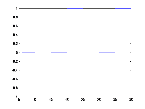 Implementing Bipolar Coding Scheme In MATLAB |
Loading
ArchivesCategories
All
|
 RSS Feed
