|
You can download complete files of the project (Noise Cancellation From Audio Signal Using Adaptive Filter Matlab Code) using following link:
http://www.junaidte14.com/product/noise-cancellation-matlab-code-using-adaptive-filter/ Your downloaded zip file will include Noise.m file, Noise.asv file, Noise.fig file, project proposal (PDF file) and also a project.pptx file. Prepared By:Muhammad Tipu Project ExplanationWhat is Noise?In signal processing, noise is a general term for unwanted modifications that a signal may suffer during capture, storage, transmission, processing, or conversion. Sometimes the word is also used to mean signals that are random and carry no useful information; even if they are not interfering with other signals or may have been introduced intentionally, as in comfort noise. Noise is any disturbance that interferes with data transmission and corrupts the quality of the signal. What is Adaptive Filter?A filter which self adjusts its transfer function is called adaptive filter. Most adaptive filters are Digital Filters. Mostly the adaptive filters are used for reducing the noise content from the sound and it is based on frequency content of sound which is our input data and the noise must be in background. The error signal are used as feedback in the form of signals in adaptive filters which is used to refine the transfer-function to-match changing-parameters. Steps for Noise Cancellation:
Matlab Codes for Above StepsRecord noise signalfunction pushbutton1_Callback(hObject, eventdata, handles)
Record audio signalfunction pushbutton2_Callback(hObject, eventdata, handles)
Add signalsfunction pushbutton3_Callback(hObject, eventdata, handles)
Filter Signalsfunction pushbutton4_Callback(hObject, eventdata, handles)
Plot signalfunction pushbutton5_Callback(hObject, eventdata, handles)
Plot noisefunction pushbutton6_Callback(hObject, eventdata, handles)
Plot mixed signalfunction pushbutton7_Callback(hObject, eventdata, handles)
Plot filtered signalfunction pushbutton8_Callback(hObject, eventdata, handles)
Plot noise cancellerfunction pushbutton9_Callback(hObject, eventdata, handles)
Play signalfunction pushbutton10_Callback(hObject, eventdata, handles)
Play noisefunction pushbutton11_Callback(hObject, eventdata, handles)
Play mixed signalfunction pushbutton12_Callback(hObject, eventdata, handles)
Play filtered signalfunction pushbutton13_Callback(hObject, eventdata, handles)
20 Comments
IntroductionSounds are a part of everyday life. From requisite hearing ability to entertainment in motion pictures and music, sounds have provided the impetus for audio engineers to increase quality of life or level of entertainment through their study and manipulation. In this project, We shall implement a digital sound effects processor; specifically, focusing on basic effects such as, delay, delay with feedback, chorus, and flanger. All these tasks will be simulated using MATLAB. Functions Performed in Audio Effect Processor
Tasks of ProjectThe DelayIn its simplest form, a delay effect takes an audio signal and plays it back after a delay time. This “echo deviceâ€, as it is otherwise known, produces a single copy of the input, delayed by anywhere from several microseconds to several seconds. A more interesting sound is produced through the use of feedback control, which takes the output of the delay and sends it back to the input, typically after multiplying by a gain less than or equal to one. This enables the sound to be repeated over and over again, becoming more attenuated with each successive loop. Theoretically, feedback can be used to produce a sound which continues forever, but practically, at some point, the sound level will fall below that of the ambient noise in the system, and the sound will no longer be audible. The ChorusSimilar to a chorus of singers, the chorus effect acts to make a single instrument sound like a group of instruments being played. Qualitatively, it is described as adding a thickness to a sound, creating a more lush sound. The chorus effect is reproducing two things: a delay and a difference in pitch between sounds, much like there would be for several instruments playing together. The pitch difference will be generated by storing the sample into larger or smaller memory blocks. In a smaller memory block, the sample is read faster thus increasing the pitch. In a larger memory block, the sample is read slower thus decreasing the pitch. The delay time for chorus is commonly between 20ms and 30ms. The delay time will be varying as well which introduces a problem. Since samples are read in at integral multiples of the sample time, a changing delay time could cause us to require a sample that is not integral. To overcome this problem, we will attempt to use linear interpolation. The FlangerFlanger is much like the chorus, but with a few subtle differences. The flanger also consists of a delay line with varying delay time, but a feedback loop is used as well to generate some distortion in the delayed sound. The common delay for flanger is between 1ms and 10ms which is what gives the input a “whooshing†sound. A low frequency oscillator will be used in this case to control the varying delay line. The same problem will occur here as it did in chorus, so linear interpolation will be used again. Basically, the implementation is similar to chorus, except for a feedback looping and adding to the original signal (see block diagram). The ControlsUsing Matlab’s GUI, a control panel will be created with slider bars to control the varying effects. For delay, the controls consist of: Delay Rate and Feedback Gain (Delay with Feedback Only.) For chorus, the controls include: Delay Rate and Seed. The seed will be just a seed for the random number generator. For flanger, the controls are: Delay Rate, Low Frequency Output Frequency, and Feedback Gain. For the EQ, the following controls will be needed: Low Band Gain, Mid Band Gain, and High Band Gain. The LFO Frequency will be used to set the frequency at which the delay line is changing. The LFO will be restricted to a range of 0.001Hz and 3.0Hz. The controls will be designed using Matlab’s Build feature which allows you to layout a GUI and add features such as drop down menus, radio buttons, as well as slider bars. Matlab Codes of FunctionsCode of Main Functionclear all; Code of Echo Functionfunction y=echo1(); Code of Multiple Echo Functionfunction y=mecho1(); Code of Reverb Function%There are three functions of Reverb as follows: Code of Flanger Functionfunction y=flanger(); Code of Low Pitch Functionfunction y=pitchshift_l(); Code of High Pitch Functionfunction y=pitchshift_h(); Code of Fade in Functionfunction y=fade_in(); Code of Fade out Functionfunction y=fade_out(); 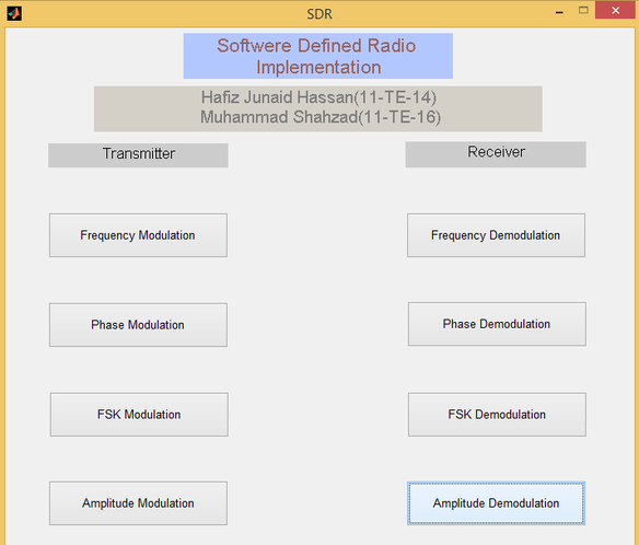 A Software Defined Radio (SDR) Implementation Using Matlab Prepared By:JUNAID HASSAN ExplanationSoftware Defined Radio (SDR) is an important subject of wireless communication. The main concept is to study this radio communication system without using expensive hardware equipment. This project is done by using Matlab software. To study radio communication system for graduate students by using hardware equipment is very expensive. This Matlab simulated “Software Defind Radio Implementation” (SDR) project gives a very good idea about how the radio communication system works. In this project different modulation and demodulation schemes have been studied. The project consists of two part i.e a transmitter part and a reciever part. In the transmitter part modulation is been done and in reciever part demodulation is done. Basic ConceptThe basic concept of this project is that first of all a signal (analog or digiatal) is defined by using a mathematical equation. Then modulation of this signal with carrier signal is achieved by using mathematical equation of that particular modulation technique. Then sound is generated of that modulated signal, which is recorded on the sound card. Note that the audio speaker of our PC works as a transmitter and our sound card, which recorded our signal’s sound is been acting as a reciever. The the main signal is extracted from the recieved signal which is then demodulated by using the mathematical equation of that particular demodulating scheme, which gives our desird information as an output. MATLAB CODESAmplitude ModulationA=0.5; % modulation index of AM modulation Amplitude DemodulationrecordModulatedSignal=audiorecorder(1000,16,1,1);% construct a recording object Frequency Modulation:%cos is considered as message signal so its integral is sine.Used here. Frequency Demodulationf_fmCarrier=1000; %frequency of FM carrier signal Frequency shift Keying (FSK) Modulationt=0.0001:.0001:1.800; Frequency Shift Keying (FSK) Demodulationt=0.0001:.0001:1.800; Phase Modulation%carrier is sine and message signal is cos Phase Demodulationf_pmCarrier=1000; %frequency of FM carrier signal |
 RSS Feed
